
Hold the Load!
Smart Rigging Requires Locking Out Hydraulic Drift
03/30/2026

In heavy lifting, raising a high tonnage load is only part of the battle. The harder engineering challenge is holding it in position. Hydraulic systems are indispensable for generating lifting force, but they are not inherently safe as a primary holding mechanism. Seals wear, valves can leak, and internal fluid bypass or thermal fluctuations can shift a load incrementally. This phenomenon, known as hydraulic drift, can be catastrophic. In critical applications like bridge lifts, industrial machinery maintenance, or structural re-leveling, even millimeter-scale movement can damage equipment, misalign precision structures, and trigger costly schedule delays.
The engineering response to hydraulic drift is a return to fundamental mechanical engagement. Modern lift-and-lock systems apply geometric logic with precision-machined components rated to hundreds or thousands of tons. Load-holding systems that rely on steel-on-steel contact, such as threads, wedges, interlocking rings, or barrels, do not drift. Once engaged, the load is physically supported by the geometry of the hardware itself, with no dependence on seal integrity, valve performance or fluid under pressure to hold position.
Integrated Mechanical Locking Across Equipment Classes
Lift-and-lock capability is not limited to a single type of equipment. Across a wide range of rigging systems, the underlying requirement is the same: the equipment must be capable of supporting the load through physical structure rather than fluid pressure alone. The mechanism by which this is achieved varies depending on the application capacity, stroke length, and required precision.
At the portable, high-capacity end of the spectrum, ring climbing cylinders use a sequence of rings and pucks to incrementally advance a 100-ton aluminum cylinder through its stroke, mechanically locking after each increment.
Other incremental lifting systems, including strand jacks, cube jacks, and large-scale jack-up towers, address higher capacity and greater stroke requirements through a sequence of lift-lock-reset cycles. Strand jacks use top and bottom wedge anchors that mechanically engage high-strength strands at each increment, providing continuous holding through the anchor system rather than through hydraulic pressure.
Cube jacks use automatic internal locking that engages as steel cribbing blocks are added. Read the case study Large-scale jack-up systems extend this approach to infrastructure-scale projects. These synchronized towers lift thousands of metric tons by incrementally sliding precision-machined steel barrels into position, maintaining level tolerances with millimeter precision across all towers simultaneously.
For general industrial use, lock nut cylinders represent the most widely deployed portable configuration. These units feature an Acme-threaded piston and a mechanical collar. Once the target height is reached, the operator threads the collar down against the cylinder body to establish a physical, pressure-independent hold. The mechanical simplicity of the lock nut design is its principal advantage: the hold is established by direct metal contact with no reliance on auxiliary valves or fluid circuits.
For applications where a purely mechanical system is preferred over hydraulics, Acme-threaded screw systems can be designed to meet specific load requirements. These systems use a self-locking thread engaged along the screw, meaning gravity alone cannot back-drive the load without an external driving force. Multiple screw jacks can also be driven with electric motors and operated via an integrated electronic control system.
Selecting the Right System for the Application
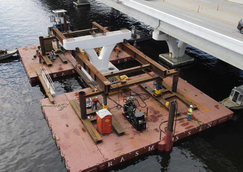
Choosing the appropriate lift-and-lock configuration depends on the capacity required at each point, the total stroke length, and how long the load must be held. Strand jacks offer a compact footprint and virtually unlimited stroke range, making them well-suited for tall or long-distance incremental lifts where a rigid structure would be impractical. Screw-based systems are preferred when the load needs to be held at all times. Tower-style systems, including cube jacks and jack-up systems (see image), are designed for the largest infrastructure lifts, where synchronization precision and sheer tonnage are the governing requirements. For a case study on a jack-up system used in a massive bridge renovation, click here.
In each case, the defining characteristic of a lift-and-lock system is that the holding function does not depend on the continued operation of the hydraulic circuit. This distinction has direct implications for personnel safety and operational risk. For projects where workers must position themselves beneath or alongside a load, a mechanical hold eliminates the hydraulic circuit as a potential failure mode. The load is therefore supported mechanically and not by pressure.

Featured Lift-and-Lock Solutions
When discussing equipment that prevents hydraulic drift, it’s helpful to have concrete examples. Engineered Rigging maintains a specialized rental fleet designed for these critical lifts.
Ring Climbing Cylinders
Ideal for confined spaces, these 100-ton cylinders feature intrinsic mechanical locking at every stage of the cycle. With a retracted height of just 12 inches and a lift range approaching 36 inches, the Holmatro Ring Climbing Cylinders are compact but powerful.

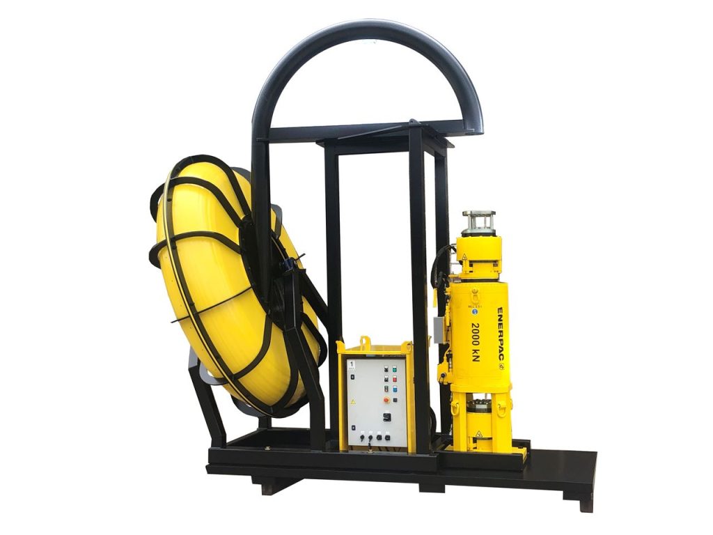
Strand Jacks
These incremental lifters utilize high-strength strands and wedge anchors. Up to 60 Enerpac strand jacks can be controlled by a single operator to handle massive loads like bridge segments.
Custom Lifting Columns
Designed by the ER engineering team to fulfill the exact specifications of the lift, these columns utilize mechanical Acme-type screws to provide self-locking, synchronized lifts of 10 tons per point.

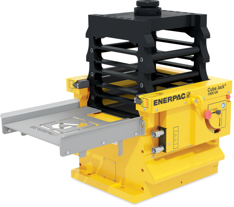
Cube Jacks
The Enerpac SCJ series offers automated internal locking and steel cribbing blocks. Engineered Rigging’s fleet includes the 50-ton SCJ-50 and the 100-ton capacity SCJ-100.
Jack-Up Systems
For massive infrastructure, the Enerpac JS-Series utilizes synchronized towers and steel barrels. Our JS500 towers can reach up to 50 feet while maintaining millimeter accuracy.

Climbing Jacks
Climbing jacks, also known as step cylinders, provide safety through every layer of the cribbing stack in a classic jack-and-pack configuration.

Put Your Project on Solid Ground
There’s a lot at stake when it comes to a lift-and-hold project: crew safety, load integrity and the project schedule. Why leave anything to chance? Engineered Rigging offers more than a bare rental fleet of heavy lifting solutions; we provide the engineering oversight to ensure your lift is synchronized, secure, and compliant. Let our engineers help you determine the optimal configuration for your next critical lift. Call 844.474.4448 or contact sales@engrigging.com to discuss your needs.